VLAN - Setup How To
VLAN in our home and home lab. How to segregate, allow traffic between VLAN. Networking is the base knowledge we need to run a home lab. This is about how not why, The way is for you to read about.


How to carve up a network and add speed, security and allowing routing between VLAN. We take a pfSense and a Level 2 Switch, and we have all we need.
Jumping in at the deep side. We have decided we need to have the following VLAN setup: Office, Lab, Servers, IoT, Kids.
Planning
To be successful, we need to plan our VLAN map. The first task is to group functions and machines. We have Office, Lab, Servers, IoT, Kids, and Guests.
VLAN IDs and IPs do not need to have any correlation at all, but it helps.
| VLAN # | Name | Description | IP nummer |
|---|---|---|---|
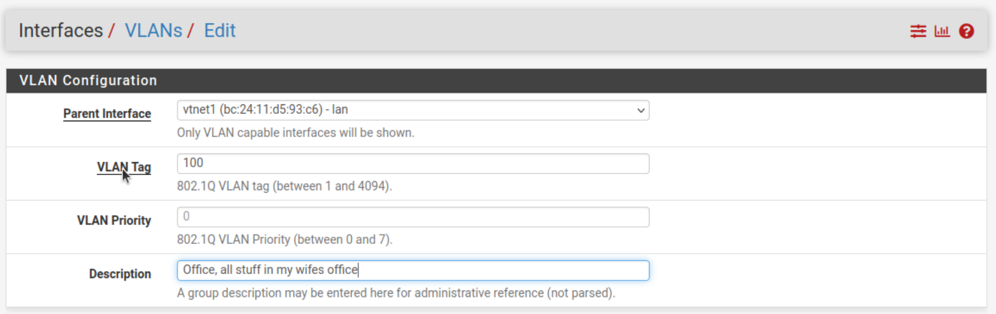
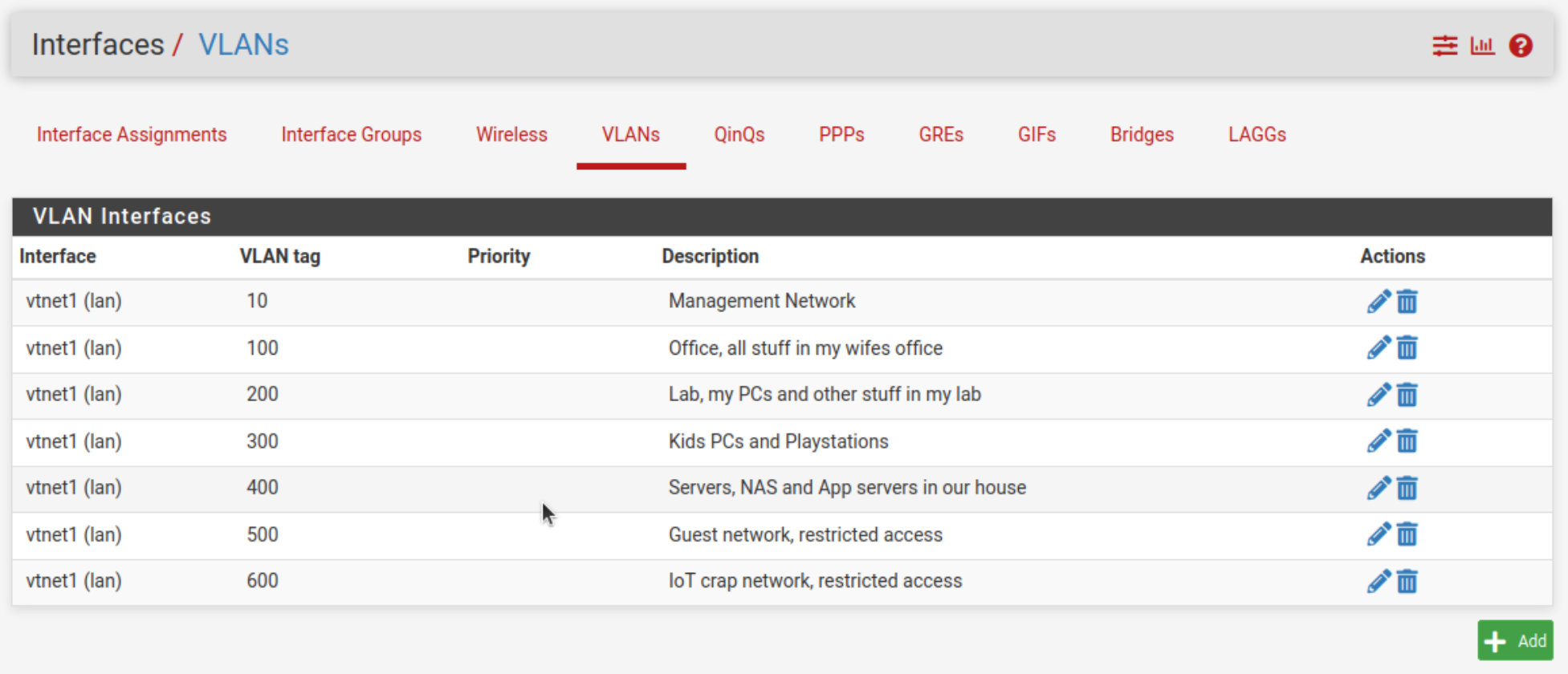
| 100 | Office | All stuff in my wifes Office | 172.16.10.0/24 |
| 200 | Lab | my PCs and other stuff in my Lab | 172.16.20.0/24 |
| 300 | Kids | PCs and Playstations | 172.16.30.0/24 |
| 400 | Servers | NAS and App servers | 172.16.40.0/24 |
| 500 | Guest | Restricted access | 192.168.50.0/24 |
| 600 | IoT | IoT crap goes here, restricted access | 172.16.60.0/24 |
Proxmox creates VLAN aware bridges with bridge-vids 2-4094. VLAN 1 is the general-use one. You can use it, but you cannot/should not modify or delete it.
Can we use them all, maybe? All depends on your switch. The normal range is 1-1005 and most allow this range. The extended range 1006–3967 is usually allowed on modern HW, and 3968-4095 are reserved on CISCO switches.
- Untagged “access” VLAN
Untagged VLAN are like traditional VLAN, where all devices share a broadcast domain. This means that every device on the VLAN receives every message sent. Untagged VLAN are used where there is no special security or classification needed to separate or isolate the VLAN traffic.- Untagged VLAN are connected to hosts (often servers) that send and receive information about VLAN. They can't tell the difference between different VLAN configurations.
- In this way, untagged VLAN have a more linear structure, moving from A to B rather than from A to B, C, and D. Generally, untagged VLAN are the default.
- Example of the untagged flow:
- Host A sends traffic to a switch, and the traffic doesn’t have a VLAN tag
- Traffic is received on access port 1 (untagged)
- Port 1 adds a VLAN tag to the frame, and the switch dictates that the frame must be sent to Host B through access port 2 (untagged)
- The VLAN tag is removed and traffic flows to Host B.
- Tagged “trunk” VLAN
When tags are used in a VLAN, devices can only communicate with other devices that have matching tags. Tagged VLAN are used when we need stricter traffic and security control.- Tagged VLAN enable switch access ports to handle more than one VLAN and separate traffic accordingly.
- Instead of the data going from one host to another, frames with a VLAN tag can be distributed from one host to many hosts, depending on port configuration. The tags indicate which packets should be sent to which VLAN.
- Example of the tagged flow:
- Host A sends a frame without a VLAN tag.
- Traffic is received on port 1 that is configured with VLAN 77, which gets added to the frame.
- The switch recognizes the VLAN tag and sends the frame to switch 2.
- Switch 2 has a tagged access port for VLAN 77, which matches the original tag.
- If at this point, VLAN tags did not match (i.e., VLAN 77 vs. VLAN 55), the frame gets dropped.
- Traffic is forwarded on to the switch 2 tagged port, which, again, checks whether the tag is permitted elsewhere and distributes the broadcast to all other VLAN 77-configured access ports.
- Once traffic reaches an untagged access port, the tag is stripped from the frame, which is sent to the final host.
CISCO VLAN rages
VLANs Numbers |
Range |
Usage |
|---|---|---|
|
1 |
Normal |
Cisco default. You can use this VLAN, but you cannot modify or delete it. |
|
2—1005 |
Normal |
You can create, use, modify, and delete these VLANs. |
|
1006—3967 |
Extended |
You can create, name, and use these VLANs. You cannot change the following parameters:
|
|
3968-4095 |
Internally allocated |
These reserved VLANs are allocated for internal device use. |
Tag based VLAN, 802.1Q
The 802.1Q VLAN is based on the IEEE802.1Q standard. The VLAN is identified by its ID. All untagged packets that reach the port are tagged according to PVID. Only frames in this VLAN can be sent to other VLAN.
Installation
We will require a Level 2 switch (managed switch), as a dumb switch will not be able to handle this setup. For Wi-Fi, a box that can handle VLAN traffic.
A pfSense box or VM. A box is better, but a VM works for me. How to install, link. We require one virtual bridge or one bypassed NIC as a minimum, but 2 is perfect.
My setup: VM: 1 GiB RAM, 1 core, 8 GiB of disk and 2 virtual bridges. This is a kind of minimum, for using more services like squid, snort, suricata or pfBlockerNG you might need more resources.
Setup VLAN Interfaces
Open your OPNsense or pfSense and go to Interfaces → Assignments → VLANs and define your VLAN set up as planned. If you set up vlnet0 as wan and vtnet1 as LAN. We will use the vtnet1 (mac-address) - lan as the base for our VLAN set-ups. Do the same thing for every VLAN network.
Assign the VLAN Interfaces
When all VLAN networks have been created, we need to assign them and setup some basic settings.
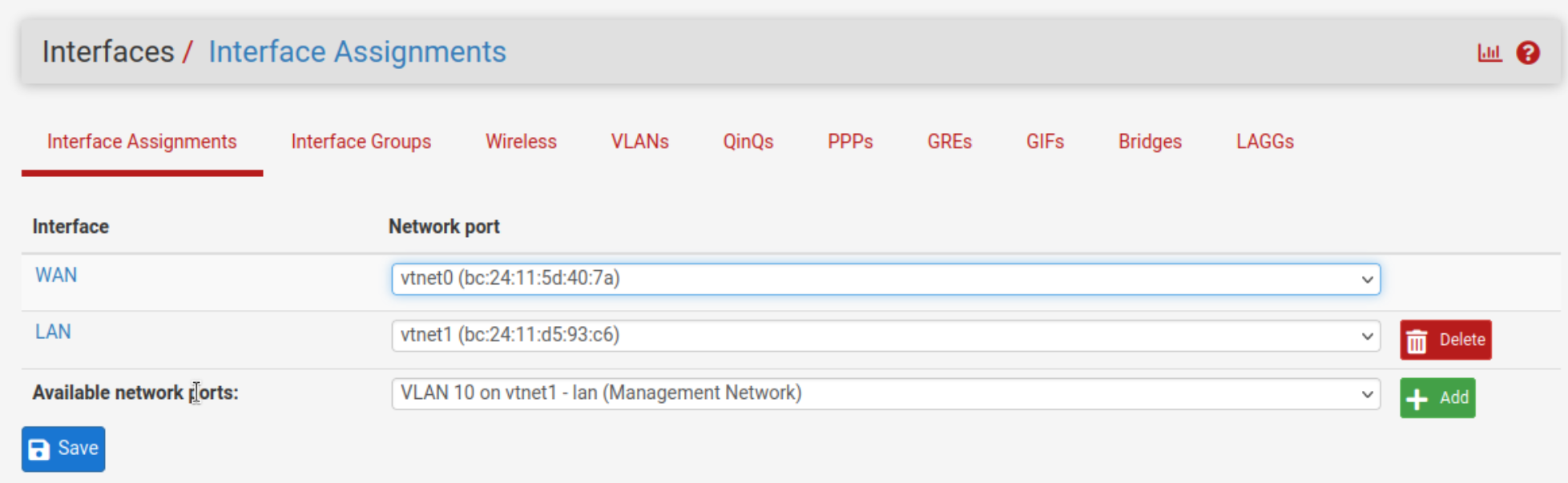
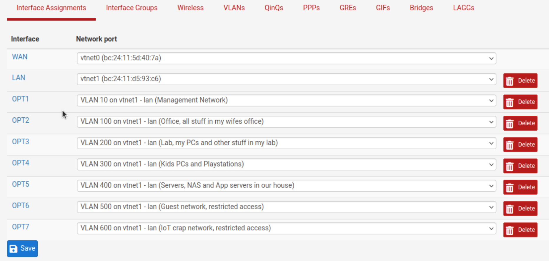
Hit save to finish setting up the link-layer.
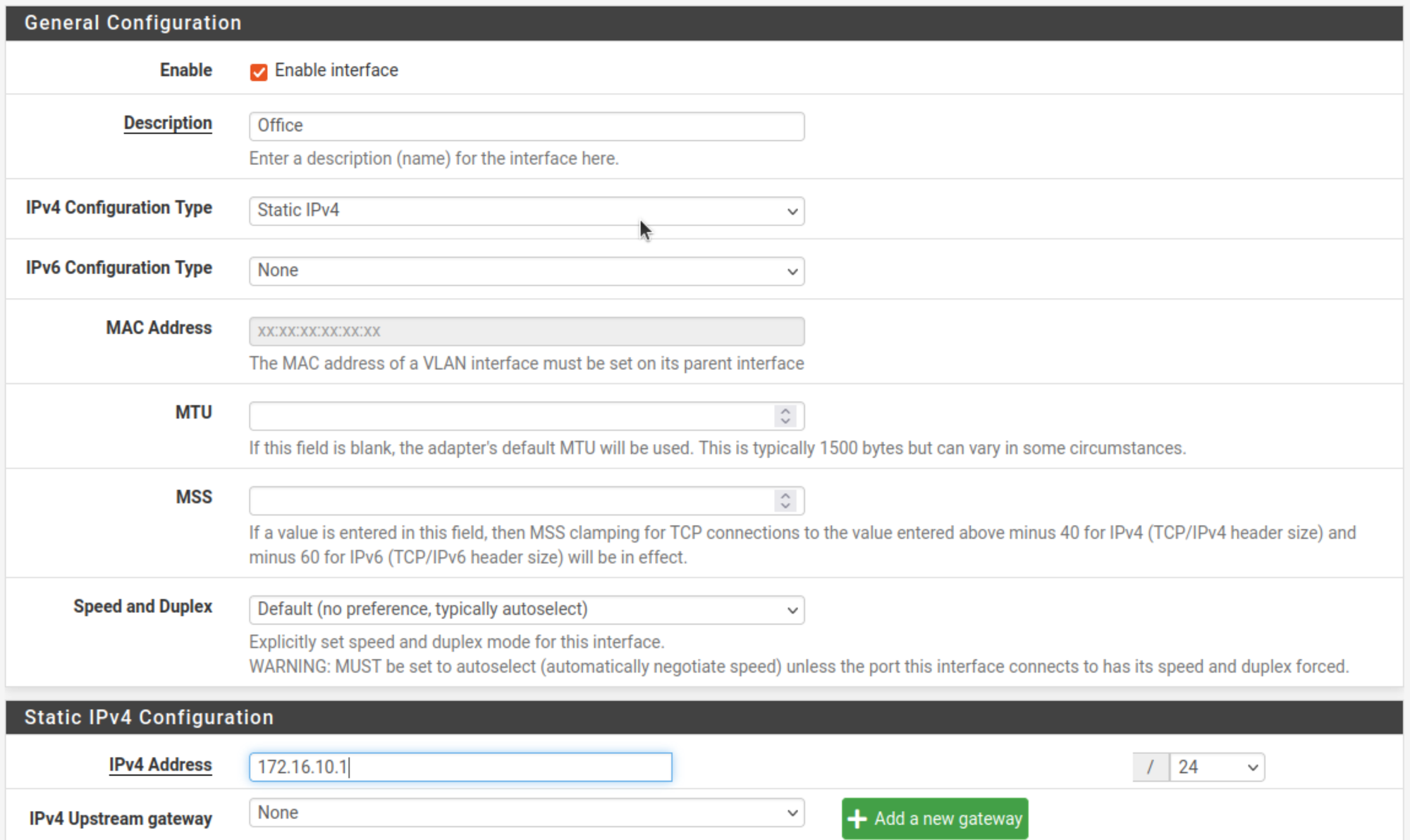
VLAN Network Configuration
Hit the OPT# to enter the Configuration of a VLAN and Enable that interface and give it the correct name in the Description, IPv4 Type (Static) and IPv4 Address (for that VLAN subnet) and the mask.
DHCP Set up
Next, we set up a DHCP server per VLAN network. Services → DHCP Server and hit each VLAN and set up the new Kea or the standard ISC (Deprecated) DHCP Server. See the System → Advanced → Networking section.⚠
⚠️ Kea is still unstable and is only for testing, see the documentation
There are two things to do, and many others you can use if you know how.
- Enable the DHCP server
- Address Pool range/Ranges, set according to your needs
Set up a Managed Switch
Since there are many ways to set up a switch, we cannot describe them all. This is merely a general description. The most important aspects to consider are:
- PVID. When adding the tag header to the received untagged packet, the switch will automatically use this PVID value as the VLAN ID of the added tag.
- Not a member, exclude the port from the current VLAN.
- Untagged, the egress rule of the traffic on this port as untagged. The switch drops the tag header before sending the packet. For example, a PC is unable to use the tag.
- Tagged, the egress rule of the traffic on this port as tagged. The switch adds the tag header before sending the packet. E.g., Proxmox bridges can utilize the tag information to send it to a VM/CT.
Firewall Rules
By using firewall rules, we can restrict or allow access to certain VLAN connected devices or total VLAN networks. We shall utilize both.
Firewall rules are complicated, very complicated.
In corporate and enterprise support organizations, there are specialized personnel doing firewall configuration and noting else 24/7. It is up to these highly skilled professionals to make, what the systems architect designed, into reality. They are also the integral part of the first response team fighting hackers and malware.
Create an Alias
The first thing to do is to set up aliases for most common things. My first is the RCF 1918 alias for all networks we can use in a home lab.

If you want to address a VLAN by its name, create an alias for each VLAN network: Management, Office, Kids, Lab, Servers, Guest and IoT, according to your setup.
Trusted networks
You can create a wide open setting for each network. Later we can disable any network. We will use Firewall Rules to tighten security.
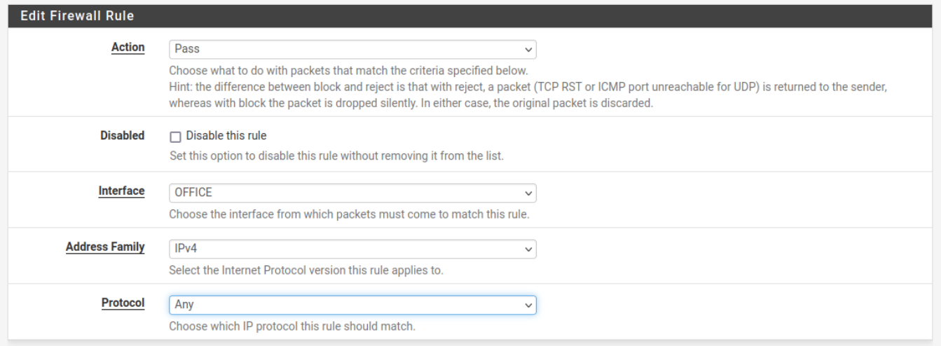
For example, I restrict the Office network to only access devices on that network and no access to the other networks is allowed from Office-Network.
Using the Firewall, we first create a blocking rule, then a Pass rule for the Office-Network.
Traffic Priority Settings
On larger networks, you need to address the priority of traffic for smooth operations. And especially for the correct working of VoIP and other audio and video services, you need to set up these priorities.
Just going from 1G to 10G to 100G may or may not help you, but the cost is high.
Port Port-based Priority Setting
| Priority | Used for | |
|---|---|---|
| 1 | Lower | Background data |
| 2 | Normal | business-critical data, email, internet, … |
| 3 | Medium | stream multimedia, … |
| 4 | High | VoIP, video, and delay sensitive data |
The packets are mapped to 4 priority levels based on ingress port.
The priority of a port is a factor that determines whether the port can be elected as the root port of a device. If all other conditions are the same, the port with the highest priority is elected as the root port.
On a spanning tree device, a port can have different priorities and play different roles in different spanning trees. As a result, data of different VLAN can be propagated along different physical paths, implementing per-VLAN load balancing. You can set port priority values based on the actual networking requirements.
Description on 802.1p priority
| Decimal | Binary | Description |
|---|---|---|
| 0 | 000 | Best effort |
| 1 | 001 | Background |
| 2 | 010 | Spare |
| 3 | 011 | Exellent effort |
| 4 | 100 | Controlled load |
| 5 | 101 | Video |
| 6 | 110 | Voice |
| 7 | 111 | Network Management |
Priority-based Flow Control (PFC) enables flow control over a unified 802.3 Ethernet media interface, or fabric, for local area network (LAN) and storage area network (SAN) technologies. PFC is intended to eliminate packet loss due to congestion on a network link. This allows loss-sensitive protocols, such as Fiber Channel over Ethernet (FCoE), to coexist with traditional loss-insensitive protocols over the same unified fabric.
- DSCP Differentiated Services Code Point (DSCP). Enabling this feature prioritizes the network traffic across the LAN based on the DSCP queue mapping on the DSCP Settings page.
- CoS Class of Service (CoS) prioritizes the network traffic based on the CoS queue mapping on the CoS Settings page.
References
IEEE [1] PFC [2] DSCP policy [3]